Removal
1.

Remove the cylinder head cover.

(Refer to Cylinder Head Assembly - "Cylinder Head Cover")

2.

Set the piston of No.1 cylinder to the TDC (top dead center) on compression stroke.

(1)

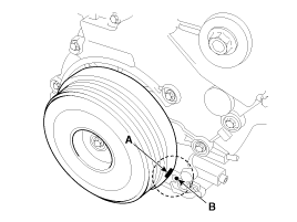
Turn the crankshaft pulley clockwise and align its groove (A) with the timing mark (B) of the timing chain cover.
note

Do not rotate engine counterclockwise.

(2)

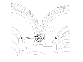
Check that the timing mark (A) of the exhaust camshaft timing gear and the timing mark (B) of the intake camshaft timing gear are aligned as shown in the illustration.
caution

If not, turn the crankshaft one revolution (360°). (Do not rotate engine counterclockwise.)
3.

Remove the timing chain cover.

(Refer to Timing System - "Timing Chain Cover")

4.

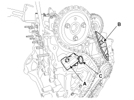
Remove the timing chain "B" auto tensioner (A) and guide (B).

note

Before removing the auto tensioner, install a set pin (C) (ø2.5 mm (0.1 in) steel wire) after compressing the tensioner.

5.

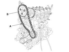
Remove the timing chain "B" (A) with the camshaft sprocket (B).

6.

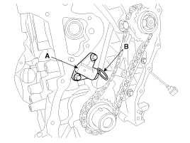
Remove the timing chain "A" auto tensioner (A).

note

Before removing the auto tensioner, install a set pin (C) (ø2.5 mm (0.1 in) steel wire) after compressing the tensioner.

7.

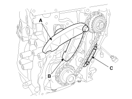
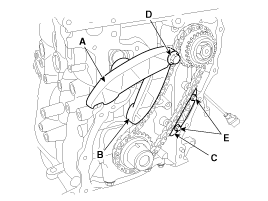
Remove the timing chain "B" lever (A), the timing chain "A" lever (B) and the timing chain “A” guide (C).

8.

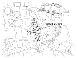
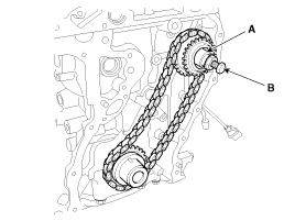
Pull the high pressure fuel pump sprocket out of the shaft.

(1)

Check the SST (09231-2B100) (A) to fix the ring gears.

(2)

After removing the high pressure fuel pump sprocket nut, install the sprocket stopper (A) of the SST (high pressure pump remover, 09331-1M100).

(3)

Rotate the bolt (B) of the SST clockwise till the high pressure fuel pump sprocket is pushed out.

9.

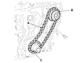
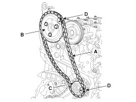
Remove the timing chain "A" (A) with the high pressure fuel pump sprocket (B) and crankshaft sprocket (C).

Installation
1.

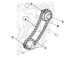
After assembling the timing chain "A" (A) with the timing marks (D) of the high pressure fuel pump sprocket (B) and the crankshaft sprocket (C) aligned, install the sprockets on each shaft. Tighten the high pressure fuel pump nut.

note

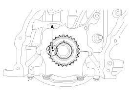
Set the timing mark (A) of the crankshaft sprocket to be aligned with the cylinder block. As a result of this, the piston of the No.1 cylinder will be at the TDC (top dead center) on compression stroke.

note

Check the SST (09231-2B100) (A) to fix the ring gears.

2.

Install the timing chain "B" lever (A), the timing chain "A" lever (B) and the timing chain “A” guide (C).

Tightening torque

Bolt (D) :

29.4 ~ 31.4 N.m (3.0 ~ 3.2 kgf.m, 21.7 ~ 23.1 lb-ft)

Bolts (E) :

9.8 ~ 11.8 N.m (1.0 ~ 1.2 kgf.m, 7.2 ~ 8.7 lb-ft)

note

Do not reuse the tensioner lever and guide fixing bolt.

If necessary, the bolt can be reused after removing hardening sealant and then applying sealant (LOCTITE 262, THREEBOND 1324N or equivalent) on the thread of the bolt.

3.

Install the timing chain "A" auto tensioner (A), and then remove the set pin (B).

Tightening torque :

9.8 ~ 11.8 N.m (1.0 ~ 1.2 kgf.m, 7.2 ~ 8.7 lb-ft)

4.

Check that the timing mark (A) of the exhaust camshaft timing gear and the timing mark (B) of the intake camshaft timing gear are aligned as shown in the illustration.

5.

After assembling the timing chain "B" (A) with the timing marks (D) of the high pressure fuel pump sprocket (C) and the camshaft sprocket (B) aligned, install the camshaft sprocket on the exhaust camshaft gear.

Tightening torque :

14.7 ~ 19.6 N.m (1.5 ~ 2.0 kgf.m, 10.8 ~ 14.5 lb-ft)

6.

Install the timing chain "B" auto tensioner (A) and guide (B), and then remove the set pin (C).

Tightening torque :

9.8 ~ 11.8 N.m (1.0 ~ 1.2 kgf.m, 7.2 ~ 8.7 lb-ft)

7.

Install the other parts in the reverse order of removal.

Яндекс.Метрика