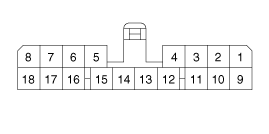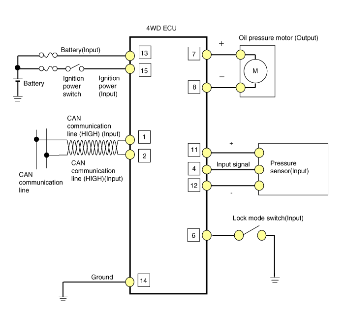

Pin | Function |
1 | CAN communication line (Low) |
2 | CAN communication line (High) |
3 | - |
4 | Pressure sensor signal(+) |
5 | - |
6 | Lock mode switch |
7 | Oil pressure motor B |
8 | Oil pressure motor A |
9 | - |
10 | - |
11 | Pressure sensor(Input) |
12 | Input sensor signal(-) |
13 | Battery power |
14 | Ground |
15 | IG power |
16 | - |
17 | - |
18 | - |
