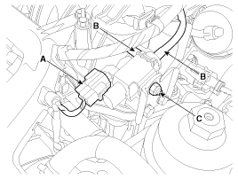
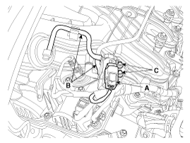
Remove the installation nut (C), and then remove the valve from the surge tank.

Turn the ignition switch OFF.
Disconnect the VIS valve connector.
Measure resistance between the VIS valve terminals 1 and 2.
Check that the resistance is within the specification.
Specification: Refer to “Specification”
Turn the ignition switch OFF and disconnect the battery negative (-) cable.
Disconnect the variable intake solenoid valve connector (A).
Disconnect the vacuum hoses (B) from the valve.
Remove the installation nut (C), and then remove the valve from the surge tank.

Turn the ignition switch OFF and disconnect the battery negative (-) cable.
Disconnect the variable intake solenoid valve connector (A).
Disconnect the vacuum hoses (B) from the valve.
Remove the installation bolts (C), and then remove the valve from the surge tank.

Install the component with the specified torques.
Note that internal damage may occur when the component is dropped. If the component has been dropped, inspect before installing.
Be careful of foreign material not to flow into the valve.
Install in the reverse order of removal.
Variable intake solenoid valve installation nut:
5.4 ~ 8.3 N.m (0.6 ~ 0.9 kgf.m, 4.0 ~ 6.2 lb-ft)