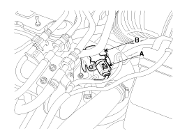
Remove the EEGR valve (B) after removing the installation bolts.

Turn the ignition switch off.
Disconnect the Electric EGR control valve connector.
Check if there is the foreign material inside the Electric EGR control valve.
Measure the resistance between 1 and 3 terminal of the Electric EGR control valve.
Check that the resistance is within the specification.
▷ Specification
Item | Specification |
Coil Resistance (Ω) | 2.3 ~ 2.7 [20℃(68℉)] |
Connect the GDS to the data link connector.
Perform the fully open and the fully closing operation of the EEGR valve by using the actuation test.
Check that the voltage is within the specification.
▷ Specification
Item | Specification |
Output voltage (V) [At the fully open position (6mm)] | 0.6 ~ 1.3 |
Output voltage (V) [At the fully closed position] | 3.6 ~ 4.3 |
Turn the ignition switch OFF and disconnect the battery (-) cable.
Disconnect the EEGR valve connector (A).
Remove the EEGR valve (B) after removing the installation bolts.

Install the component with the specified torques.
Note that internal damage may occur when the component is dropped. In this case, use it after inspecting.
Installation is reverse of removal.
Electric EGR control valve installation bolt:
7.8 ~ 11.8 N.m (0.8 ~ 1.2kgf.m, 5.8 ~ 8.7 lb-ft)
After replacing the Electric EGR control valve, MUST perform the "Component Change Routine" procedure. Otherwise trouble related with engine performance or emission control may occur until ECM learning about the component is over.
Turn the ignition switch OFF.
Connect the GDS to Data Link Connector (DLC).
Turn ignition switch ON.
Select "Vehicle, Model year, Engine, System".
Select "Vehicle S/W Management".
Select "Component Change Routine".
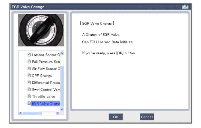
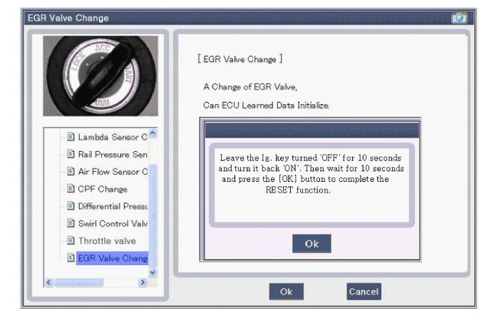
Select " EGR Valve Change".
Perform the procedure in accordance with the message.

