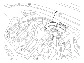
Disconnect the brake vacuum hose (A).
Use fender covers to avoid damaging painted surfaces.
To avoid damage, unplug the wiring connectors carefully while holding the connector portion.
Mark all wiring and hoses to avoid misconnection.
For release the fuel system pressure before remove the engine assembly, start the engine without fuel pump relay.
And then turn off the ignition switch after engine stops.
Disconnect the battery "-" terminal.
Remove the engine cover.
Remove the air duct.
(Refer to Intake and Exhaust System - "Air cleaner")
Remove the battery and battery tray.
(Refer to Engine Electrical System - "Battery")
Disconnect the brake vacuum hose (A).

Remove the air cleaner assembly.
(Refer to Intake and Exhaust System - "Air cleaner")
Remove the engine room under cover.
Loosen the drain plug, and drain the coolant. Remove the radiator cap to speed draining.
(Refer to Cooling System - "Coolant")
Remove the radiator upper hose (A) and lower hose (B).
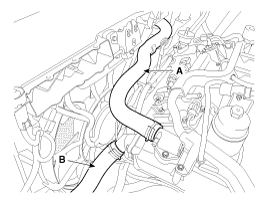
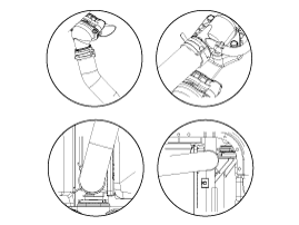
When installing radiator hoses, install as shown in illustrations.
Remove the engine control module (ECM) assembly.
(Refer to Engine Control/Fuel System - "Engine Control Module (ECM)")
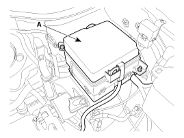
Remove the fuse box cover (A).
Disconnect the fuse box main wiring connector (A) and battery "+" cable (B).
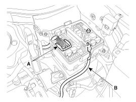
Remove mounting nuts of the main wiring protector (A).
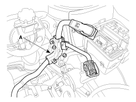
Disconnect the front connector (A).
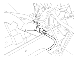
Remove the battery wiring protector (A).
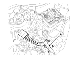
Remove the transaxle wire harness connectors and control cable from the transaxle.
(Refer to Automatic transaxle System - "Automatic transaxle")
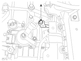
Remove the transaxle earth cable (A).
Disconnect the ATF cooler hose.
(Refer to Automatic Transaxle System - "Automatic Transaxle")
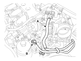
Disconnect the purge control solenoid valve (PCSV) (A) and fuel hose (B).
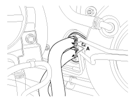
Disconnect the heater hoses (A).
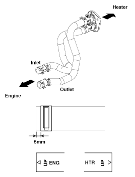
When installing the heater hoses, install as shown in illustrations.
Recover the refrigerant and then remove the high pressure pipe and low pressure pipe.
(Refer to Heating, Ventilation, Air Conditioning - "Compressor")
Remove the propeller shaft in case of the 4WD vehicle type.
(Refer to 4 Wheel Drive System - "Front Transfer Assembly")
Remove the front muffler.
(Refer to Intake And Exhaust System - "Muffler")
Remove the front wheels.
Remove the shock absorbers, the stabilizer bar links and the tie rod ends.
(Refer to Suspension System - "Front Stabilizer Bar")
Disconnect the drive shafts from the axle hub.
(Refer to Drive Shaft and Axle - "Front Driveshaft")
In case of the hydraulic power steering (HPS) type, disconnect the power steering oil return hose for drain the oil, and then remove the hose that connecting between the power steering oil pump assembly and the reservoir tank.
(Refer to Steering System - "Power steering gear box")
Support the sub frame with a floor jack, and then remove the sub frame mounting bolts.
(Refer to Suspension System - "Sub Frame")
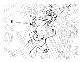
Disconnect the engine earth cable, and then remove the engine mounting support bracket (A).
Tightening torque
Bolts (B) & Nut (C):
88.3 ~ 107.9 N.m (9.0 ~ 11.0 kgf.m, 65.1 ~ 79.6 lb-ft)
Nut (D):
88.3 ~ 107.9 N.m (9.0 ~ 11.0 kgf.m, 65.1 ~ 79.6 lb-ft)
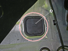
Remove the srvice cover (A).
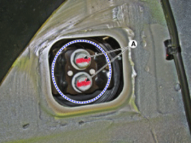
Remove the transaxle mounting fixing bolt (A).
Tightening torque:
88.3 ~ 107.9 N.m (9.0 ~ 11.0 kgf.m, 65.1 ~ 79.6 Ib-ft)
Remove the engine and transaxle assembly by lifting vehicle.
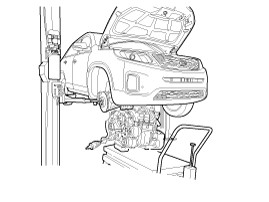
When remove the engine and transaxle assembly, be careful not to damage any surrounding parts or body components.