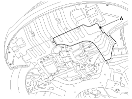
Remove the under cover (A).
Tightening torque:
6.9 ~ 10.8 N.m (0.7 ~ 1.1 kgf.m, 5.1 ~ 8.0 lb-ft)
Check signal waveform of Input & output speed sensor using the GDS.
Specification: Refer to "Signal Wave Form" section.
Remove the battery and the battery tray.
(Refer to "Charging system" in EE group.)
Remove the under cover (A).
Tightening torque:
6.9 ~ 10.8 N.m (0.7 ~ 1.1 kgf.m, 5.1 ~ 8.0 lb-ft)

Replace new gasket and the plug after draining the automatic transaxle fluid by removing the drain plug. (Refer to "Hydraulic system (Fluid)" in this group)
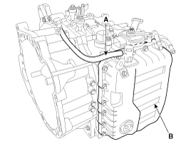
Remove the air breather hose (A).
Remove the valve body cover (B).
Tightening torque:
13.7 ~ 15.7 N.m (1.4 ~ 1.6 kgf.m, 10.8 ~ 11.6 lb-ft)
Remove installation bolts in the engine compartment first and then remove others under the vehicle.
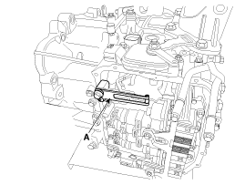
Remove the plate and the detent spring (A) after removing the bolt.
Tightening torque:
11.8 ~ 15.7 N.m (1.2 ~ 1.6 kgf.m, 8.7 ~ 11.6 lb-ft)
Remove the bolt (3ea) after disconnecting the solenoid valve connector (B) and the oil temperature sensor connector (A).
Tightening torque:
9.8 ~ 11.8 N.m (1.0 ~ 1.2 kgf.m, 7.2 ~ 8.7 lb-ft)
Be careful not to damage the harness lock connector.
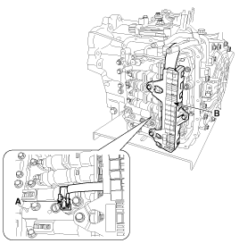
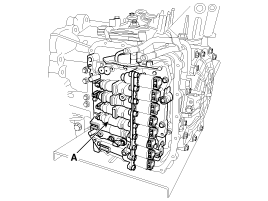
Remove the valve body assembly (A).
Tightening torque:
9.8 ~ 11.8 N.m (1.0 ~ 1.2 kgf.m, 7.2 ~ 8.7 lb-ft)
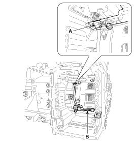
Disconnect the input & output speed sensor connector(A).
Remove the input & output speed sensor (B) after removing the bolts (2ea).
Tightening torque:
9.8 ~ 11.8 N.m (1.0 ~ 1.2 kgf.m, 7.2 ~ 8.7 lb-ft)
Installation is the reverse of removal.
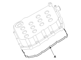
Replace the gasket (A) before reinstalling the valve body cover.
Adding automatic transaxle fluid.
(Refer to "Hydraulic system (Fluid)" in this group)
Perform TCM learning after replacing the automatic transaxle to prevent slow automatic transaxle response, jerky acceleration and jerky startup.
(Refer to "Automatic transaxle control system (Repair procedures)" in this group)