Inspect the cam height.
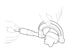
Using a micrometer, measure the cam height.
Cam height
Intake : 43.85 mm (1.7264 in)
Exhaust : 42.85 mm (1.6870 in)

If the cam lobe height is less than specified, replace the camshaft.
Inspect the cam height.
Using a micrometer, measure the cam height.
Cam height
Intake : 43.85 mm (1.7264 in)
Exhaust : 42.85 mm (1.6870 in)

If the cam lobe height is less than specified, replace the camshaft.
Inspect the camshaft journal clearance.
Clean the bearing caps and camshaft journals.
Place the camshafts on the cylinder head.
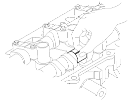
Lay a strip of plastigage across each of the camshaft journal.

Install the bearing caps and tighten the bolts with specified torque.
Tightening torque
M6 bolts :
11.8 ~ 13.7 N.m (1.2 ~ 1.4 kgf.m, 8.7 ~ 10.1 lb-ft)
M8 bolts :
18.6 ~ 22.6 N.m (1.9 ~ 2.3 kgf.m, 13.7 ~ 16.6 lb-ft)
Do not turn the camshaft.
Remove the bearing caps.
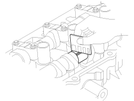
Measure the plastigage at its widest point.
Bearing oil clearance
Standard :
0.027 ~ 0.058 mm (0.0011 ~ 0.0023 in)
Limit : 0.1 mm ( 0.0039 in)

If the oil clearance is greater than specification, replace the camshaft.
If the oil clearance is still greater than specification after camshaft replacement, replace the bearing caps and cylinder head as a set.
Inspect the camshaft end play.
Install the camshafts.
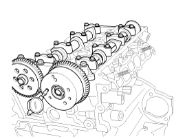
Using a dial indicator, measure the end play while moving the camshaft back and forth.
Camshaft end play :
0.1 ~ 0.2 mm (0.0039 ~ 0.0079 in)

If the end play is greater than specification, replace the camshaft.
If the end play is still greater than specification after camshaft replacement, replace the bearing caps and cylinder head as a set.
Remove the camshafts.
Inspect the CVVT assembly.
Fix the CVVT assembly with its camshaft in a vice.
Check that the CVVT assembly will not turn. If it is not turned, it is in normal condition.
Apply vinyl tape to all the parts except the one hole.
Using an air gun, apply the pressure, 147.10 kPa (1.5 kg/cm², 21.33 psi) in the hole.
This makes the lock pin in maximum retarded state released.
Wrap around it with a shop rag and the likes, because the oil splashes.
After releasing the pin, you can turn the CVVT assembly for advance by hand.
If there was too much air leakage, the pin can not be released
Under the condition of 3), turn the CVVT assembly to the advance angle side with your hand.
Depending on the air pressure, the CVVT assembly will turn to the advance side.
Also, under the condition that the pressure can be hardly applied because of the air leakage from the port, there may be the case that the lock pin could be hardly released.
Except the position where the lock pin meets at the maximum delay angle, let the CVVT assembly turn back and forth and check the movable range and that there is no disturbance.
Standard : Movable smoothly in the range about 25˚
Turn the CVVT assembly with your hand counterclockwise and lock it at the maximum delay angle position.