3.
Remove the ground line after removing the bolt (A).
Air cleaner assembly and air duct.
(Refer to Engine Mechanical System - "Air cleaner")
Battery and battery tray.
(Refer to Engine Electrical System - "Battery")
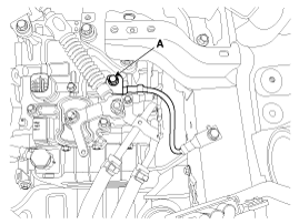
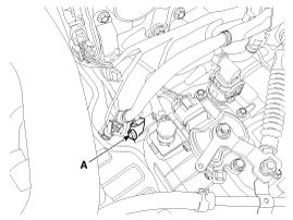
Remove the ground line after removing the bolt (A).
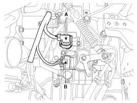
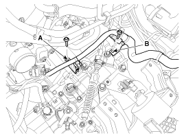
Dissconnect the solenoid valve connector (A) and inhibitor switch connector (B).
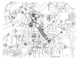
Remove the control cable (C) after removing the nut (A) and the bolt (B).
Tightening torque:
(A) 9.8 ~ 13.7 N.m (1.0 ~ 1.4 kgf.m, 7.2 ~ 10.1 lb-ft)
(B) 14.7 ~ 21.6 N.m(1.5 ~ 2.2 kgf.m, 10.9 ~ 15.9 lb-ft)
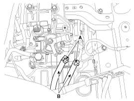
Disconnect the hose (B) after removing the automatic transaxle fluid cooler hose clamp (A).
Remove the wiring mounting bolt (A).
Tightening torque:
9.8 ~ 11.8 N.m (1.0 ~ 1.2 kgf.m, 7.2 ~ 8.7 lb-ft)
Remove the solenoid valve connector and inhibitor switch connector wiring mounting bracket (A)and(B).
Tightening torque:
Bolt (A) :
9.8 ~ 11.8 N.m (1.0 ~ 1.2 kgf.m, 7.2 ~ 8.7 lb-ft)
Bolt (B) :
14.7 ~ 21.6 N.m(1.5 ~ 2.2 kgf.m, 10.9 ~ 15.9 lb-ft)
Remove the cowl top cover.
(Refer to Body - "Cowl Top Cover")
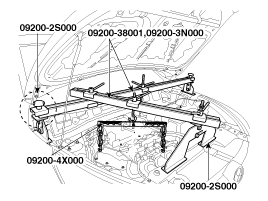
Assemble the engine support fixture.
(Refer to Special Service Tools-"Engine support fixture assembly drawing")
Using the engine support fixture (beam No.: 09200-38001 or 09200-3N000, supporter No.: 09200-2S000, adapter No.: 09200-4X000), hold the engine and transaxle assembly safely.
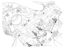
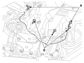
Remove the automatic transaxle upper mounting bolt (A-2ea) and the starter motor mounting bolt (B-2ea).
Tightening torque:
(A) 42.2 ~ 54.0 N.m (4.3 ~ 5.5 kgf.m, 31.1 ~ 39.8 lb-ft)
(B) 49.0 ~ 63.7 N.m (5.0 ~ 6.5 kgf.m, 36.2 ~ 47.0 lb-ft)
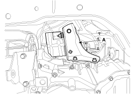
Remove the mounting cover (A).
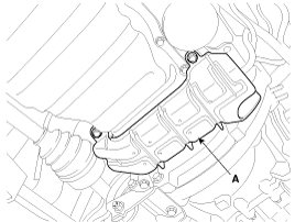
Remove the automatic transaxle mounting bracket bolts (A).
Tightening torque:
88.3 ~ 107.9 N.m (9.0 ~ 11.0 kgf.m, 65.1 ~ 79.8 lb-ft)
Remove the automatic transaxle support bracket (A).
Tightening torque:
58.8 ~ 78.5 N.m (6.0 ~ 8.0 kgf.m, 43.4 ~ 57.9 lb-ft)
Lift the vehicle with a jack.
Remove the under cover (A).
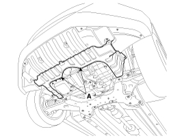
Remove the drive shaft assembly.
(Refer to Driveshaft and Axle - "Front Driveshaft")
Remove the heat protector (A).
Tightening torque:
19.6 ~ 29.4 N.m (2.0 ~ 3.0 kgf.m, 14.5 ~ 21.7 lb-ft)
Remove the air guide bracket (A).
Tightening torque:
8.8 ~ 13.7 N.m (0.9 ~ 1.4 kgf.m, 6.5 ~ 10.1 lb-ft)
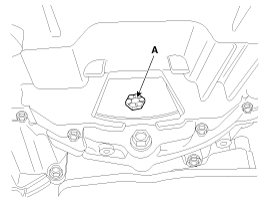
Remove the dust cover (A).
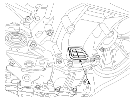
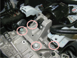
Remove the torque converter mounting bolts(A) with rotating the crankshaft.
Tightening torque:
45.1 ~ 52.0 N.m (4.6 ~ 5.3 kgf.m, 33.3 ~ 38.3 lb-ft)
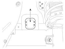
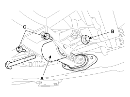
Remove the roll stopper (A).
Tightening torque:
Nut (B):
107.9 ~ 127.5 N.m (11.0 ~ 13.0 kgf.m, 79.6 ~ 94.0 lb-ft)
Bolt (C):
49.0 ~ 63.7 N.m (5.0 ~ 6.5 kgf.m, 36.2 ~ 47.0 lb-ft)
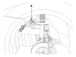
Remove the mounting bolt (A, B) after supporting the transaxle by a jack.
Tightening torque:
(A) 42.2 ~ 53.9 N.m (4.3 ~ 5.5 kgf.m, 31.1 ~ 39.8 lb-ft)
(B) 42.2 ~ 48.1 N.m (4.3 ~ 4.9 kgf.m, 31.1 ~ 35.4 lb-ft)
Remove the transaxle while slowly lower the jack.
Be careful not to damage other system or parts near by when removing the transaxle assembly.
Install in the reverse order of removal.
If the oil seal on the transaxle case side is damaged and fluid is leaking, replace the oil seal with a new unit. When installing the new oil seal, use the specialized tool (oil seal installer, 09452-26100).
After replacement or reinstallation procedure of the automatic transaxle assembly, must perform procedures below.
Adding automatic transaxle fluid.
(Refer to Hydraulic System - "Fluid")
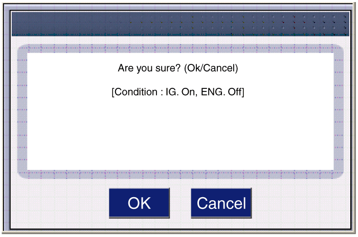
After replacing the automatic transaxle, clear the Diagnostic Trouble Code(DTC) using the GDS tool. DTC cannot be cleared by disconnecting the battery.
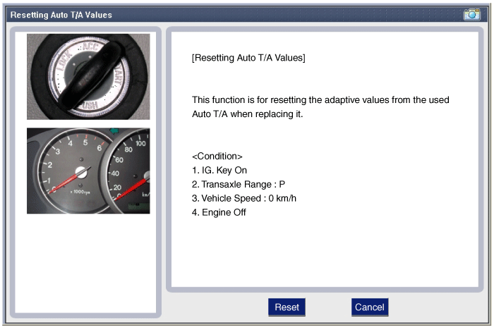
When replacing the automatic transaxle, reset the automatic transaxle's values by using the GDS.
Perform TCM learning after replacing the transaxle to prevent slow transaxle response, jerky acceleration and jerky startup.
(Refer to Automatic Transaxle Control System - "Repair procedures")
