2.
Disconnect the main wiring connectors and harness clamps and remove the wiring protector.
Disconnect the battery negative terminal.
Disconnect the main wiring connectors and harness clamps and remove the wiring protector.
Remove the engine room under cover.
(Refer to Engine And Transaxle Assembly - "Engine Room Under Cover")
Drain the coolant.
(Refer to Cooling System - "Coolant")
Remove the air cleaner assembly.
(Refer to Intake and Exhaust System - "Air Cleaner")
Remove the battery and battery tray.
(Refer to Engine Electrical System - "Battery")
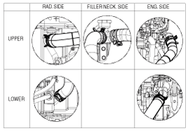
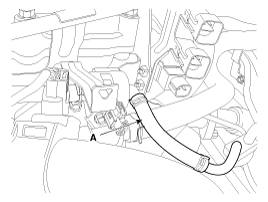
Remove the radiator upper hoses (A).
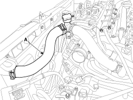
Install the radiator hoses as shown illustrations.
Remove the intake manifold with the electronic throttle control (ETC) module.
(Refer to Intake And Exhaust System - "Intake Manifold")
Remove the exhaust manifold.
(Refer to Intake And Exhaust System - "Exhaust Manifold")
Remove the timing chain.
(Refer to Timing System - "Timing Chain")
Remove the power steering oil pump assembly. (With HPS only)
(Refer to Steering System - "Power Steering Oil Pump")
Remove the delivery pipe assembly.
(Refer to Engine Control/Fuel System - "Delivery Pipe")
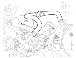
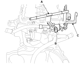
Disconnect the brake vacuum hose (A).
Disconnect the vapor hose (A) from the purge control solenoid valve (PCSV).
Remove the vacuum pipe (A) with the purge control solenoid valve (PCSV) (B) and remove the module hanger bracket (C).
Tightening torque
Vacuum pipe bolts :
9.8 ~ 11.8 N.m (1.0 ~ 1.2 kgf.m, 7.2 ~ 8.7 lb-ft)
Remove the water temperature control assembly.
(Refer to Cooling System - "Water Temperature Control Assembly")
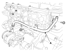
Remove the water pipe (A).
Tightening torque
M6 bolt and nuts :
9.8 ~ 11.8 N.m (1.0 ~ 1.2 kgf.m, 7.2 ~ 8.7 lb-ft)
M8 bolt :
18.6 ~ 23.5 N.m (1.9 ~ 2.4 kgf.m, 13.7 ~ 17.4 lb-ft)
Remove the oil level gauge pipe.
(Refer to Lubrication System - "Oil Level Gauge & Pipe")
Remove the intake oil control valve (OCV).
(Refer to Engine Control/Fuel System - "CVVT Oil Control Valve (OCV)")
Remove the camshaft position sensor (CMPS).
(Refer to Engine Control/Fuel System - "Camshaft Position Sensor (CMPS)")
Remove the spark plugs.
(Refer to Engine Electrical System - "Spark Plug")
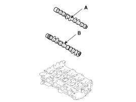
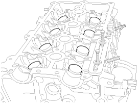
Remove the Intake CVVT assembly (A) and Exhaust camshaft sprocket (B).
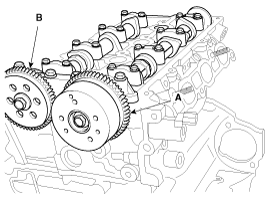
When removing the CVVT assembly and camshaft sprocket bolts, hold the camshaft at designated point (A) using a wrench to prevent the camshaft from rotating.
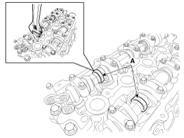
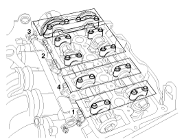
Remove the camshaft bearing caps. Loosen the bearing cap bolts in the sequence shown.
Remove the exhaust camshaft (A) and the intake camshaft (B).
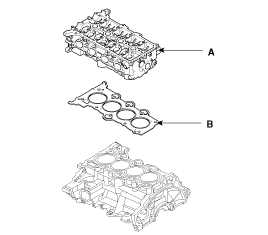
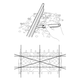
Remove the cylinder head.
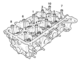
Uniformly loosen and remove the 10 cylinder head bolts, in several passes, in the sequence shown.

Head warpage or cracking could result from removing bolts in an incorrect order.
Lift the cylinder head (A) from the cylinder block and put the cylinder head on wooden blocks on a bench.
Be careful not to damage the contact surfaces of the cylinder head and cylinder block.
Remove the cylinder head gasket (B).
Identify MLA(Mechanical lash adjuster), valves, valve springs as they are removed so that each item can be reinstalled in its original position.
Remove the MLAs (A).
When removing MLAs, mark all the MLAs for their rearrangement.
Remove the valves.
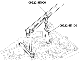
Using the SST (09222 - 3K000, 09222 - 3K100), compress the valve spring and remove the retainer lock.
Remove the spring retainer.
Remove the valve spring.
Remove the valve.
Remove the valve stem seal.
Using a magnetic finger, remove the spring seat.
Do not reuse the valve stem seals.
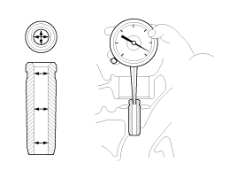
Inspect for flatness.
Using a precision straight edge and feeler gauge, measure the surface the contacting the cylinder block and the manifolds for warpage.
Flatness of cylinder head gasket surface
Less than 0.05 mm (0.0020 in.) for total area
Less than 0.02 mm (0.0008 in.) for a section of 100 mm (3.9370 in.) X 100 mm (3.9370 in.)
Inspect for cracks.
Check the combustion chamber, intake ports, exhaust ports and cylinder block surface for cracks. If cracked, replace the cylinder head.
Inspect the valve stems and valve guides.
Using a caliper gauge, measure the inner diameter of valve guide.
Valve guide inner diameter :
5.500 ~ 5.512 mm (0.2165 ~ 0.2170 in)
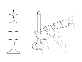
Using a micrometer, measure the outer diameter of valve stem.
Valve stem outer diameter
Intake : 5.465 ~ 5.480 mm (0.2152 ~ 0.2157 in)
Exhaust : 5.458 ~ 5.470 mm (0.2149 ~ 0.2154 in)
Subtract the valve stem outer diameter measurement from the valve guide inner diameter measurement.
Valve stem- to-guide clearance
Intake : 0.020 ~ 0.047 mm (0.0008 ~ 0.0019 in)
Exhaust : 0.030 ~ 0.054 mm (0.0012 ~ 0.0021 in)
If the clearance is greater than specification, replace the valve or the cylinder head.
Inspect the valves.
Check the valve is ground to the correct valve face angle.
Check that the surface of valve for wear.
If the valve face is worn, replace the valve.
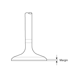
Check the valve head margin thickness.
If the margin thickness is less than minimum, replace the valve.
Margin
Standard
Intake : 1.1 mm (0.0433 in)
Exhaust : 1.26 mm (0.0496 in)
Check the length of valve.
Valve length
Standard
Intake : 93.15 mm (3.6673 in)
Exhaust : 92.60 mm (3.6457 in)
Check the surface of valve stem tip for wear.
If the valve stem tip is worn, replace the valve.
Inspect the valve seats and guide.
Check the valve seat for evidence of overheating and improper contact with the valve face. If the valve seat is worn, replace the cylinder head.
Check the valve guide for wear. If the valve guide is worn, replace the cylinder head.
Inspect the valve springs.
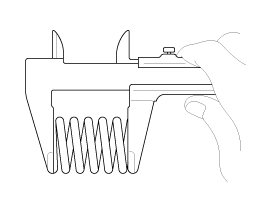
Using a steel square, measure the out-of-square of valve spring.
Using a vernier calipers, measure the free length of valve spring.
Valve spring
Standard
Free height : 45.1 mm (1.7755 in)
Out of square : Less than 1.5˚
Thoroughly clean all parts to be assembled.
Before installing the parts, apply fresh engine oil to all sliding and rotating surface.
Replace oil seals with new ones.
Install the valves.
Install the spring seats.
Using the SST (09222 - 2B100), push in a new oil seal.
Do not reuse old valve stem oil seals.
Incorrect installation of the seal could result in oil leakage past the valve guides.
Install the valve, valve spring and spring retainer, after applying engine oil at the end of each valve.
When installing valve springs, the enamel coated side should face the valve spring retainer.
Using the SST (09222 - 3K000, 09222 - 3K100), compress the spring and install the retainer locks.
After installing the valves, ensure that the retainer locks are correctly in place before releasing the valve spring compressor.
When fixing the SST on the cylinder head, do not tighten the bolts excessively.
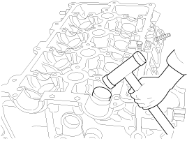
Lightly tap the end of each valve stem two or three times with the wooden handle of a hammer to ensure proper seating of the valve and retainer lock.
Install the MLA(Mechanical lash adjuster)s.
Check that the MLA rotates smoothly by hand.
All the MLAs must be installed in its original position.
Thoroughly clean all parts to be assembled.
Always use a new cylinder head and manifold gasket.
Always use a new cylinder head bolt.
The cylinder head gasket is a metal gasket. Take care not to bend it.
Rotate the crankshaft, set the No.1 piston at TDC.
Install the cylinder head assembly.
Before installing, remove the hardened sealant from the cylinder block and cylinder head surface.
Before installing the cylinder head gasket, apply sealant on the upper surface of the cylinder block and reassemble the gasket within five minutes.
Refer to the illustration for applying sealant.
Width : 2.0 ~ 3.0 mm (0.0787 ~ 0.1181 in.)
Position : 1.0 ~ 1.5 mm (0.0394 ~ 0.0591 in.)
Specification : TB 1217H or LOCTITE 5900H
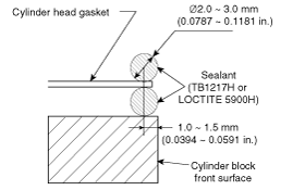
After installing the cylinder head gasket on the cylinder block, apply sealant on the upper surface of the cylinder head gasket and reassemble in five minutes.
Place the cylinder head carefully not to damage the gasket.
Install the cylinder head bolts with washers.
Tighten the 10 cylinder head bolts, in several passes, in the sequence shown.
Tightening torque :
29.4 N.m (3.0 kgf.m, 21.7 lb-ft) + 90° + 90°
Do not reuse the cylinder head bolts.
Place the exhaust camshaft (A) and the intake camshaft (B).
Install the camshaft bearing caps. Tighten the bearing cap bolts in the sequence shown.
Tightening torque
M6 bolts :
11.8 ~ 13.7 N.m (1.2 ~ 1.4 kgf.m, 8.7 ~ 10.1 lb-ft)
M8 bolts :
18.6 ~ 22.6 N.m (1.9 ~ 2.3 kgf.m, 13.7 ~ 16.6 lb-ft)
Install the intake CVVT assembly (A) and exhaust camshaft sprocket (B).
Tightening torque :
63.7 ~ 73.5 N.m (6.5 ~ 7.5 kgf.m, 47.0 ~ 54.2 lb-ft)
When installing the CVVT assembly and camshaft sprocket bolts, hold the camshaft at designated point (A) using a wrench to prevent the camshaft from rotating.
Install the other parts in the reverse order of removal.
