7.
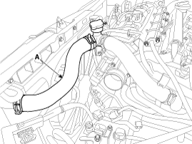
Disconnect the radiator upper hose (A).
note
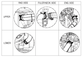
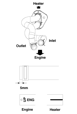
Install the radiator hoses as shown illustrations.
Engine removal is not required for this procedure.
Use Fender cover to avoid damaging painted surfaces.
To avoid damaging the cylinder head, wait until the engine coolant temperature drops below normal temperature before removing it.
When handling a metal gasket, take care not to fold the gasket or damage the contact surface of the gasket.
To avoid damage, unplug the wiring connectors carefully while holding the connector portion.
Mark all wiring and hoses to avoid misconnection.
Turn the crankshaft pulley so that the No. 1 piston is at top dead center (TDC) .
Remove the engine cover.
Disconnect the battery negative terminal.
Remove the air duct and air cleaner assembly.
(Refer to Intake and Exhaust System - "Air Cleaner")
Remove the battery and battery tray.
(Refer to Engine Electrical System - "Battery")
Remove the engine room under cover.
(Refer to Engine And Transaxle Assembly - "Engine Room Under Cover")
Loosen the drain plug and drain the coolant. Open the radiator cap to make rapid draining.
(Refer to Cooling System - "Coolant")
Disconnect the radiator upper hose (A).
Install the radiator hoses as shown illustrations.
Disconnect the A/C compressor connector.
(Refer to Heating, Ventilation Air conditioning - "Compressor")
Disconnect the alternator connector and the cable from the alternator “B” terminal.
(Refer to Engine Electical System - "Alternator")
Disconnect the engine coolant temperature sensor (ECTS).
(Refer to Engine Control/Fuel System - "Engine Coolant Temperature Sensor")
Disconnect the electronic throttle control (ETC) connector.
(Refer to Engine Control/Fuel System - "ETC System")
Disconnect the manifold absolute pressure sensor (MAPS) connector and Intake air temperature sensor (IATS) connector.
(Refer to Engine Control/Fuel System - "Manifold Absolute Pressure Senosr")
(Refer to Engine Control/Fuel System - "Intake Air Temperature Senosr")
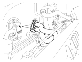
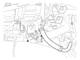
Disconnect the brake vacuum hose (A).
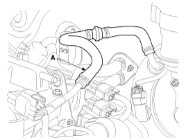
Disconnect the heater hose (A).
When installing the heater hoses, install as shown in illustrations.
Disconnect the purge control solenoid valve (PCSV) hose (A).
Remove the intake manifold.
(Refer to Intake And Exhaust System - "Intake Manifold")
Remove the fuel delivery pipe assembly.
(Refer to Engine Control/Fuel System - "Delivery Pipe")
Remove the exhaust manifold.
(Refer to Intake And Exhaust System - "Exhaust Manifold")
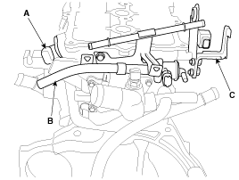
Disconnect the camshaft position sensor (CMPS) connector (A) and remove the purge control solenoid valve (PCSV) bracket (B) and the module hanger bracket (C).
Remove the cylinder head cover.
(Refer to Cylinder Head Assembly - "Cylinder Head Cover")
Remove the timing chain cover.
(Refet to Timing System - "Timing Chain Cover")
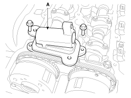
Remove the exhaust oil control valve (OCV) adapter (A).
Remove the timing chain.
(Refet to Timing System - "Timing Chain")
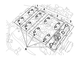
Remove the camshaft bearing caps (A) with the order below.
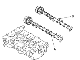
Remove the intake camshaft (A) and exhaust camshaft (B).
Remove the continuous variable valve timing (CVVT).
(Refer to Cylinder Head Assembly - "CVVT & Camshaft")
Disconnect the bypass hose, and then remove the water temperature control assembly.
(Refer to Cooling System - "Water Temperature Control Assembly")
Remove the water pipe
(Refer to Cooling System - "Water Temperature Control Assembly")
Remove the intake oil control valve (OCV).
(Refer to Engine Control/Fuel System - "CVVT Oil Control Valve (OCV)")
Remove the spark plug.
(Refer to Engine Electrical System - "Spark Plug")
Remove the cylinder head bolts, then remove the cylinder head with the gasket.
Uniformly loosen and remove the 10 cylinder head bolts, in several passes, in the sequence shown.
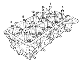
Head warpage or cracking could result from removing bolts in an incorrect order.
Lift the cylinder head from the cylinder block and put the cylinder head on wooden blocks.
Be careful not to damage the contact surfaces of the cylinder head and cylinder block.
