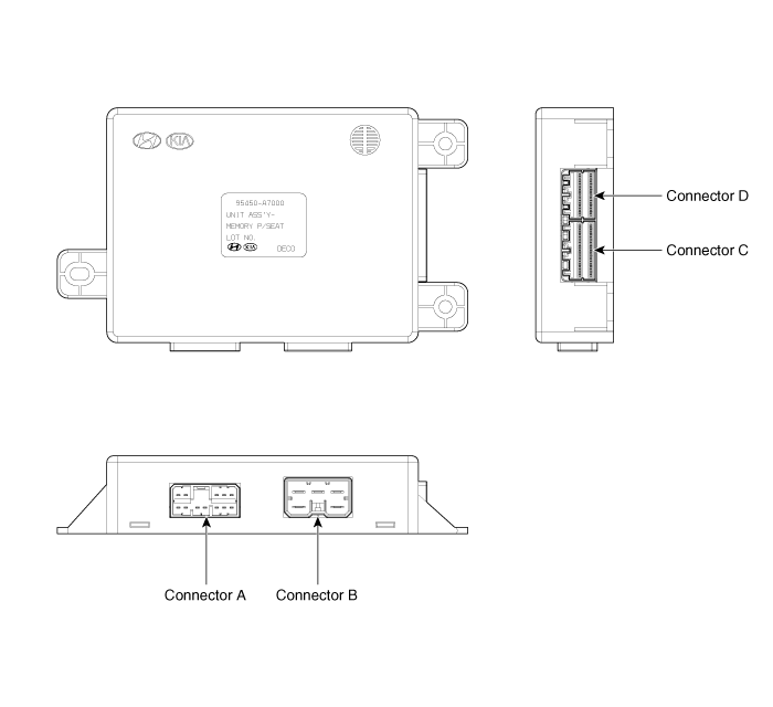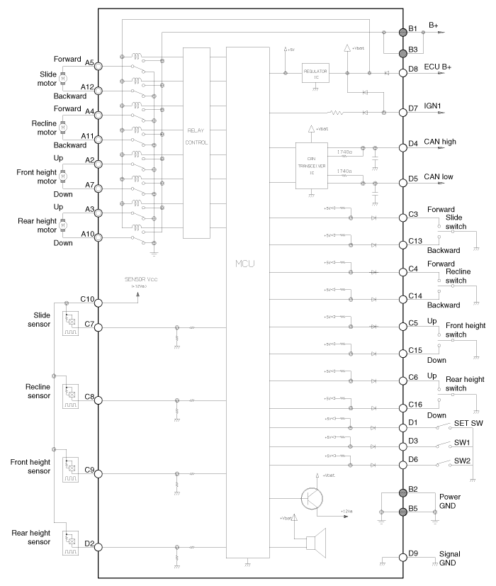


No. | Signal Name | I/O | Contents | Remark |
A1 | - | - | - |
|
A2 | FRT height motor up | O | Front height motor up output |
|
A3 | RR height motor up | O | Rear height motor up output |
|
A4 | Recline motor FWD | O | Recline motor Forward output |
|
A5 | Slide motor FWD | O | Slide motor Forward output |
|
A6 | - | - | - |
|
A7 | FRT height motor down | O | Front height motor down output |
|
A8 | - | - | - |
|
A9 | - | - | - |
|
A10 | RR height motor down | O | Rear height motor down output |
|
A11 | Recline motor BWD | O | Recline motor backward output |
|
A12 | Slide motor BWD | O | Slide motor backward output |
|
B1 | B+(Power) | I | Power B+ for operating motor |
|
B2 | GND (Power) | I | Power GND for operating motor |
|
B3 | B+(Power) | I | Power B+ for operating motor |
|
B4 | - | - | - |
|
B5 | GND (Power) | I | Power GND for operating motor |
|
C1 | - | - | - |
|
C2 | - | - | - |
|
C3 | Slide FWD manual switch | I | Slide forward manual switch input | On : GND |
C4 | Recline FWD manual switch | I | Recline forward manual switch input | On : GND |
C5 | FRT height up manual switch | I | Front height up manual switch input | On : GND |
C6 | RR height up manual switch | I | Rear height up manual switch input | On : GND |
C7 | Slide motor sensor | I | Slide motor sensor input | Pulse signal |
C8 | Recline motor sensor | I | Recline motor sensor input | Pulse signal |
C9 | FRT height motor sensor | I | Front height motor sensor input | Pulse signal |
C10 | Sensor Vcc(Seat) | O | VCC for operating sensor | 5V |
C11 | - | - | - |
|
C12 | - | - | - |
|
C13 | Slide RR manual switch | I | Slide rear manual switch input | ON : GND |
C14 | Recline RR manual switch | I | Recline rear manual switch input | ON : GND |
C15 | FRT height down manual switch | I | Front height down manual switch input | ON : GND |
C16 | RR height down manual switch | - | Rear height down manual switch input | ON : GND |
C17 | - | - | - |
|
C18 | - | - | - |
|
C19 | - | - | - |
|
C20 | - | - | - |
|
D1 | SET switch | I | SET switch input | ON : GND |
D2 | RR height up sensor | I | Rear height up motor sensor | Pulse signal |
D3 | SW1 switch | I | SW1 switch input | ON : GND |
D4 | CAN high | I/O | CAN high BUS |
|
D5 | CAN low | I/O | CAN low BUS |
|
D6 | SW2 switch | I | SW2 switch input | ON : GND |
D7 | IGN1 | I | IGN1 input | BAT |
D8 | B+(ECU) | I | ECU power input | BAT |
D9 | GND(SIGNAL) | I | Sinal ground |
|
D10 | - | - | - |
|
D11 | - | - | - |
|
D12 | - | - | - |
|
D13 | - | - | - |
|
D14 | - | - | - |
|
D15 | - | - | - |
|
D16 | - | - | - |
|
