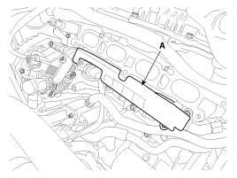
Remove the injector foam (A).

Connect the GDS on the Data Link Connector (DLC).
Measure the output voltage of the RPS at idle and various engine speed.
Condition | Output Voltage (V) |
Idle | Approx. 1.2 |
1,500 rpm | 2.2 ~ 2.5 |
6,300 rpm | Approx. 3.0 |
Turn the ignition switch OFF and disconnect the battery negative (-) cable.
Release the residual pressure in fuel line (Refer to “Release Residual Pressure in Fuel Line” in this group).
When removing the fuel pump fuse, a Diagnostic Trouble Code (DTC) may occur. Delete the code with the GDS after completion of “Release Residual Pressure in Fuel Line” work.
Remove the intake manifold. (Refer to Engine Mechanical System - “Intanke Manifold”)
Remove the injector foam (A).

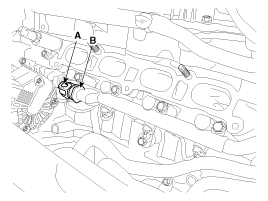
Disconnect the rail pressure sensor connector (A), and then remove the sensor (B) from the delivery pipe.

Install the component with the specified torques.
Note that internal damage may occur when the component is dropped. If the component has been dropped, inspect before installing.
Install in the reverse order of removal.
Rail Pressure Sensor Installation:
30.0 ~ 35.0 N.m (3.0 ~ 3.6 kgf.m, 22.1 ~ 25.8 lb-ft)