1.
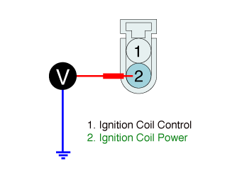
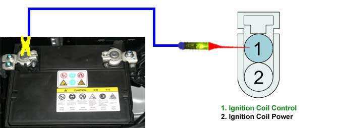
Measure the voltage between "Power" terminal of "IGNITION COIL" harness connector and chassis ground at IG key "ON" after disconnecting "IGNITION COIL" connector.
■ Specification : B+
Measure the voltage between "Power" terminal of "IGNITION COIL" harness connector and chassis ground at IG key "ON" after disconnecting "IGNITION COIL" connector.
■ Specification : B+
Is the measured voltage value normal ?
 | ▶ Go to "Ignition coil control circuit inspection" procedure as below. |
 | ▶ Check for open/poor connection/short to ground between "IGN COIL 15A" FUSE and "Power" terminal of "IGNITION COIL" harness connector. |
Connect the red tongs of LED circuit tester to battery (+) and the probe of it to "Control" terminal of "IGNITION COIL" harness connector after disconnecting "IGNITION COIL" connector.
Perform the actuation test of "Ignition coil #1~#4" by using GDS.
Check LED lamp of the circuit tester while performing the actuation test.
■ Specification : The LED lamp blinks during the actuation test.
Does the LED lamp of the circuit tester blink normally ?
| ▶ Go to "Primary ignition signal waveform inspection" procedure as below. |
| ▶ Check for open/poor connection/short to ground between "Ignition Coil Control" terminal of "ECM/PCM" harness connector and "Control" terminal of "IGNITION COIL" harness connector. |
Select oscilloscope function on the GDS and Connect channel "A" of the VMI to "Control" terminal of "ECM/PCM" harness connector.
Measure the signal waveform of the primary ignition at IG key "START".
■ Reference signal waveform
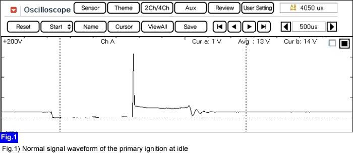
Is the measured signal waveform of the primary ignition normal ?
| ▶ Click on "Spark plug" item for more details. ▶ Click on "MAPS" item for more details. ▶ Click on "TPS" item for more details. |
| ▶ Check for open/poor connection/short to ground between "Ignition Coil Control" terminal of "ECM/PCM" harness connector and "Control" terminal of "IGNITION COIL" harness connector. |
