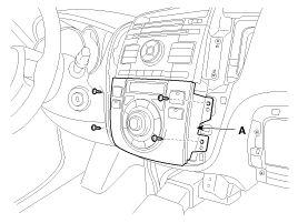
After removing the screws, remove the heater control module (A).
Disconnect the negative(-) battery terminal.
Remove the air vent.
(Refer to the BD group - "Crash pad")
After removing the screws, remove the heater control module (A).

Disconnect the door lock switch connectors (A).
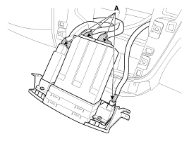
Remove the door lock switch (A) after loosening the screws.
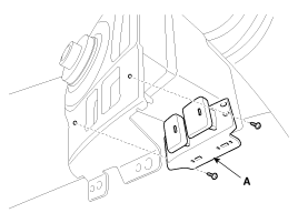
Be careful not to damage door trim panel and door module mounting hooks
Install the door lock switch.
Install the heater control module.
Install the air vent.
Install the negative (-) battery terminal.
Make sure that the power window switch module connectors are plugged properly.
Check that the power window switch and door lock switch operate normally.
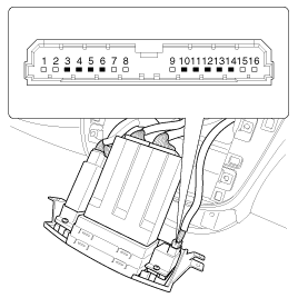
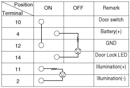
Check that continuity exists between the terminals after turning the assist seat heater switch ON.
It will be able to diagnose defects of door lock with GDS quickly. GDS can operates actuator forcefully, input/output value monitoring and self diagnosis.
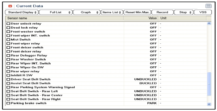
Select "Current data", if you will check current data of power door lock system. It provides input/output status of BCM.
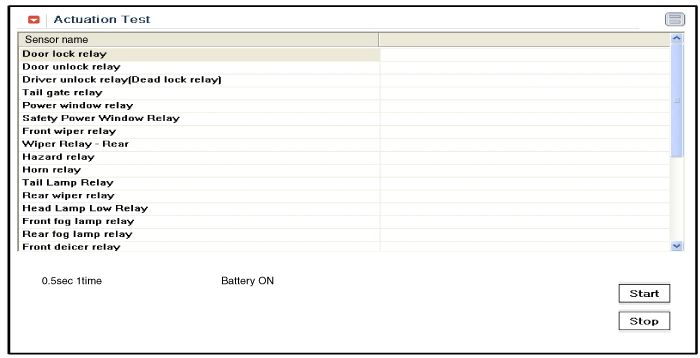
If you will check the power door lock operation forcefully, select "Actuation test".
To check the DTC of the door lock, select "Diagnostic trouble codes".