Has a problem been found?
 | ▶ Repair as necessary and then go to "Verification of Vehicle Repair" procedure. |
 | ▶ Go to "Charging System Inspection" procedure. |
Many malfunctions in the electrical system are caused by poor harness and terminals.
Faults can also be caused by interference from other electrical systems, and mechanical or chemical damage.
Thoroughly check all connectors (and connections) for looseness, bending, corrosion, contamination, deterioration, and/or damage.
Has a problem been found?
 | ▶ Repair as necessary and then go to "Verification of Vehicle Repair" procedure. |
 | ▶ Go to "Charging System Inspection" procedure. |
Connect GDS to Data Link Connector(DLC).
Engine "ON"
Turn on all electrical load such as headlamp, rear window defogger, and A/C.
Maintain engine speed at about 1500 RPM.
Monitor "Battery Positive Voltage" parameter on "Current Data" with GDS.
Specification : Approx. 14 V
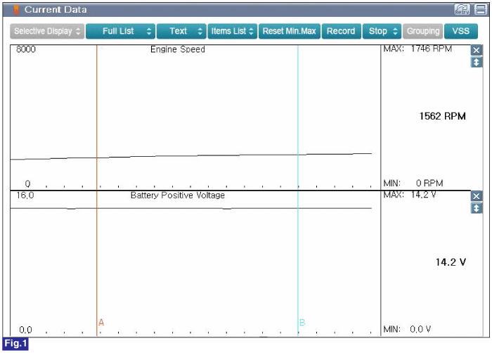
Fig.1) Normal Battery Voltage at 1500rpm
Is parameter displayed within specification?
 | ▶ Go to "Verification of Vehicle Repair" procedure. |
 | ▶ Check the tension of drive belt, ENG RPM, fuse, terminal of battery, all terminals of alternator are in good condition and check for damaged harness and poor connection between alternator and battery. ▶ Go to "Power Circuit Inspectionr" procedure. |
Ignition "OFF"
Disconnect HECU connector.
Ignition "ON"
Measure voltage between Pin No.1(Power) terminal/Pin No.32(On/Start Power) terminal of HECU harness connector and chassis ground.
Specification : B+
Is measured value within specification?
 | ▶ Go to "Ground Circuit Inspection" procedure. |
 | ▶ Repair the circuit and then go to "Verification of vehicle Repair" procedure. |
Ignition "OFF"
Disconnect Battery (-) terminal.
Disconnect HECU connector.
Measure resistance between Pin No.13(Ground) and Pin No.38(Ground) terminal of HECU harness connector and chassis ground.
Specification : Approx. below 1 Ω
Is measure value within specification?
 | ▶ Retry all of procedures once again. If the HECU is in abnormal condition, replace it. Go to "Verification of Vehicle Repair" procedure. |
 | ▶ Repair the circuit and then go to "Verification of vehicle Repair" procedure. |
In case of replacing HECU, perform following procedures.
1. Perform "Auto Detected Configuration Reset(ESP(ESC) Only)" for Varian Coding.
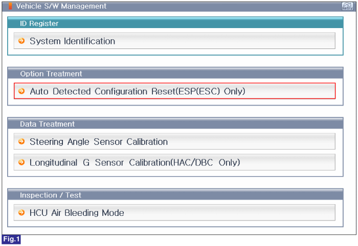
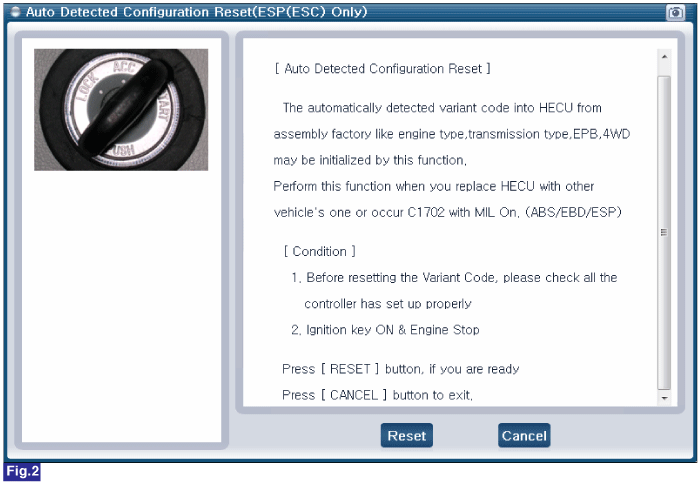
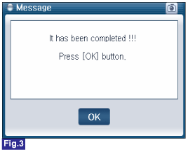
Fig.1) 1st Screen of Vehicle S/W Management
Fig.2) 1st Screen of "Auto Detected Configuration Reset(ESP(ESC) Only)"
Fig.3) Final Screen of "Auto Detected Configuration Reset(ESP(ESC) Only)"
2. Perform "Steering Angle Sensor Calibration" for steering angle sensor.
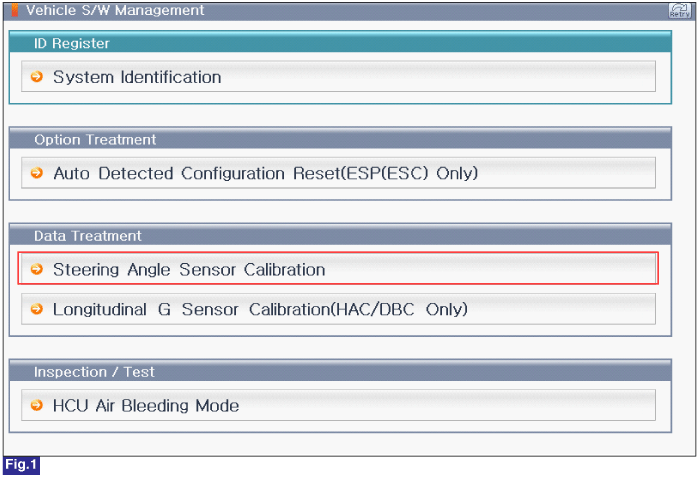
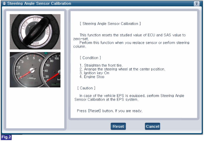
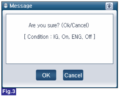
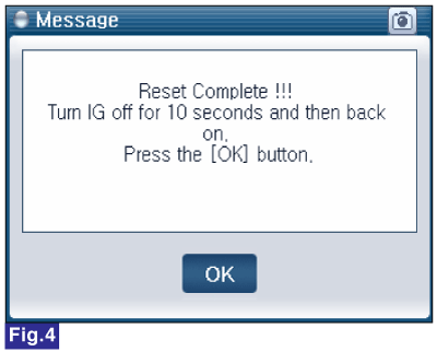
Fig.1) S/W Mangement Main Screen
Fig.2) Steering Angle Sensor Calibration Screen
Fig.3) Condition Check Screen
Fig.4) Complete
3. "Longitudinal G-Sensor Calibration(HAC/DBC Only)" for longitudinal sensor offset correction.
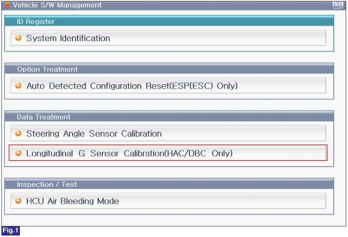
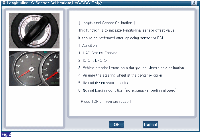
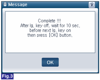
Fig.1) 1st Screen of Vehicle S/W Management
Fig.2) 1st Screen of "Longitudinal G-Sensor Calibration(HAC/DBC Only)"
Fig.3) Final Screen of "Longitudinal G-Sensor Calibration(HAC/DBC Only)"
4. "HCU Air Bleeding Mode" for removing air in the HECU.
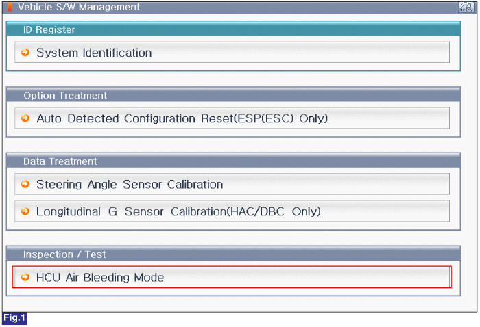
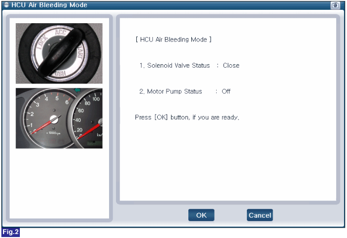
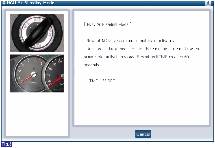
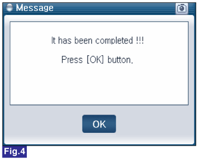
Fig.1) 1st Screen of Vehicle S/W Management
Fig.2) 1st Screen of "HCU Air Bleeding Mode"
Fig.3) 2st Screen of "HCU Air Bleeding Mode"
Fig.4) Complete