Is measure value within specification?
 | ▶ If no problems were found with the circuits or connectors, replace the HECU. Go to "Verification of Vehicle Repair" procedure. |
 | ▶ If no problems were found with the circuits or connectors, replace the Clutch switch. Go to "Verification of Vehicle Repair" procedure. |
In case of replacing HECU, perform following procedures.
1. Perform "Auto Detected Configuration Reset(ESP(ESC) Only)" for Varian Coding.
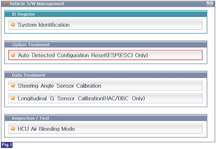
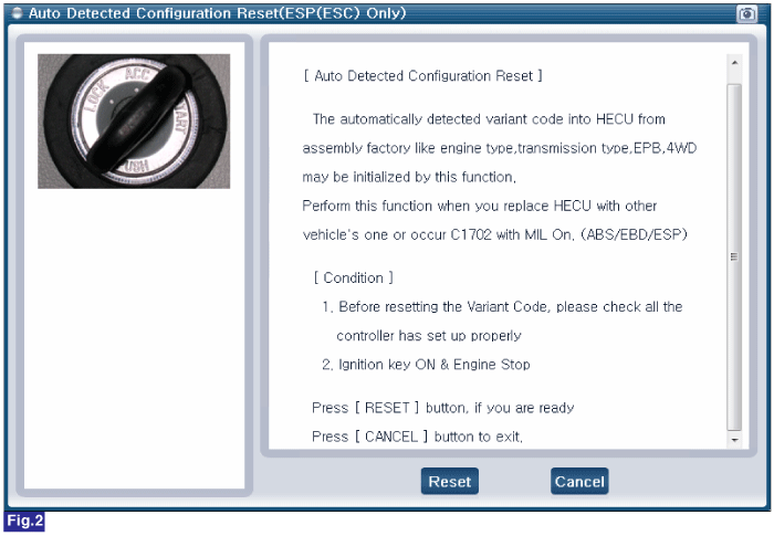
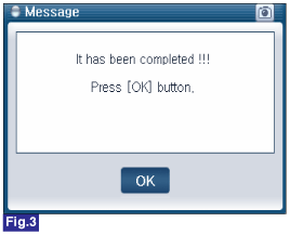
Fig.1) 1st Screen of Vehicle S/W Management
Fig.2) 1st Screen of "Auto Detected Configuration Reset(ESP(ESC) Only)"
Fig.3) Final Screen of "Auto Detected Configuration Reset(ESP(ESC) Only)"
2. Perform "Steering Angle Sensor Calibration" for steering angle sensor.
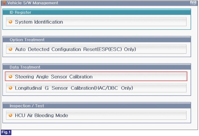
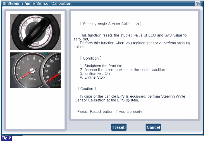
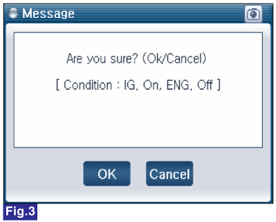
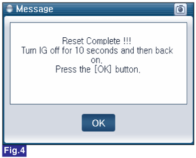
Fig.1) S/W Mangement Main Screen
Fig.2) Steering Angle Sensor Calibration Screen
Fig.3) Condition Check Screen
Fig.4) Complete
3. "Longitudinal G-Sensor Calibration(HAC/DBC Only)" for longitudinal sensor offset correction.
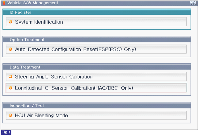
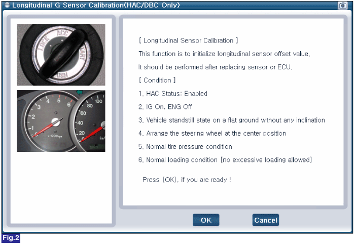
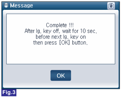
Fig.1) 1st Screen of Vehicle S/W Management
Fig.2) 1st Screen of "Longitudinal G-Sensor Calibration(HAC/DBC Only)"
Fig.3) Final Screen of "Longitudinal G-Sensor Calibration(HAC/DBC Only)"
4. "HCU Air Bleeding Mode" for removing air in the HECU.
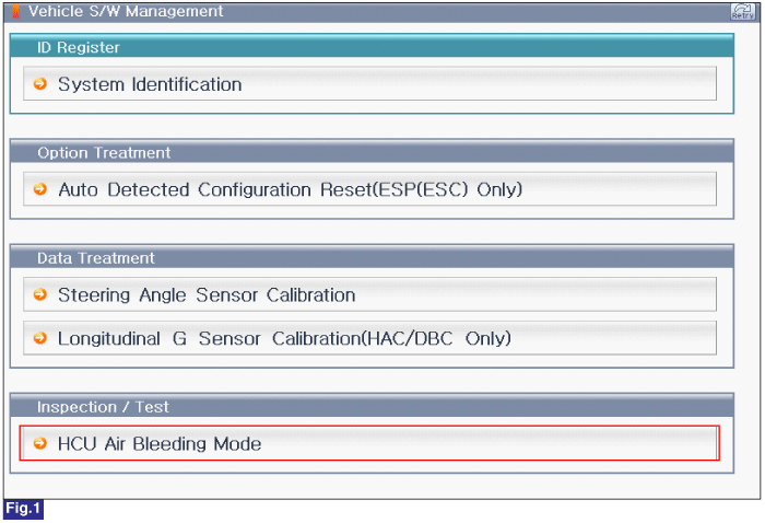
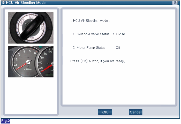
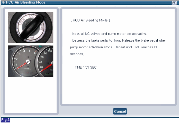
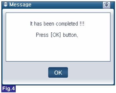
Fig.1) 1st Screen of Vehicle S/W Management
Fig.2) 1st Screen of "HCU Air Bleeding Mode"
Fig.3) 2st Screen of "HCU Air Bleeding Mode"
Fig.4) Complete
